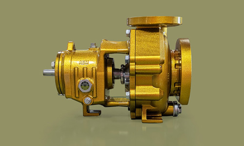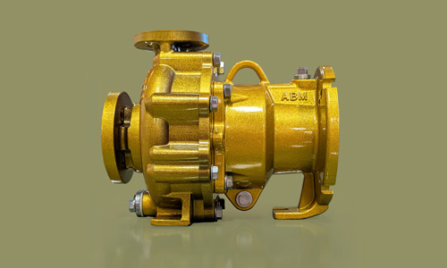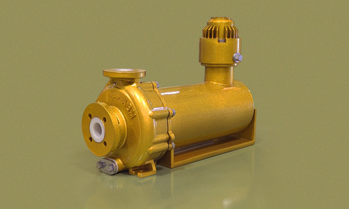
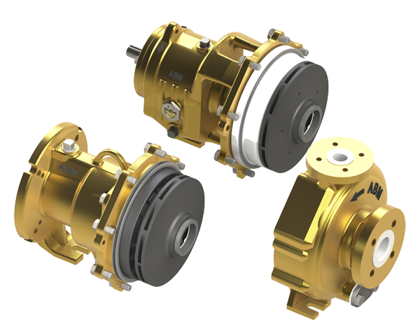
AP-M pumps are horizontal, end-suction, sealless, thrust balanced, fluoropolymer-lined, ANSI centrifugal pumps that conform to ASME B73.3 sealless standards. The standard pump is close-coupled to the motor and employs a magnetic coupling to drive the impeller. The pump is hermetically sealed, eliminating leaks and fugitive emissions.
With its durable construction and precision manufacturing, AP-M pumps are perfect for demanding applications. This results in a pump that is virtually maintenance-free, with no seal replacement required, and is suitable for a wide range of applications, including chemical processing, water treatment, and pharmaceutical manufacturing, where high purity and reliability are essential.
Operating Parameters
- Flows to 525 gpm (119 m³/h) (Group 1. Group 2 coming soon)
- Heads to 320 ft (98 m) (Group 1. Group 2 coming soon)
- Pressures to 300 psi (20.7 bar)
- Temperatures from −20 to 250°F (−29 to 121°C)
- Power rated to 30 hp (22 kW) (Group 1. Group 2 coming soon)
- Maximum Viscosity: Typical applications up to 125 cP, contact ABM for higher viscosity
- Maximum Solids: size depends on the pump size, 30% by volume
Typical Applications
ABM ETFE-lined sealed and sealless pump products are ideal for any application within their operating envelope.
- Chemical processing
- Acid transfer
- Water/waste chemical treatment
- Pharmaceutical manufacturing
- Electronics manufacturing
- Hydrocarbon processing
- Reactor feed
- Chlor-alkali
- Scrubber systems
- Food and beverage
- Tank car loading/unloading
- Metal finishing: pickling, etching, and plating
Features and Benefits
Superior Chemical Resistance:
The wetted materials inside the pump are made from ETFE plastic, which is highly inert to most chemicals, protecting the ductile iron exterior components that give AP-M pumps the strength and rigidity of traditional alloy pumps.
All external metal surfaces are painted with a two-part epoxy primer and urethane topcoat for the ultimate resistance to corrosion and UV resistance. This paint system’s quality far exceeds that found on comparable pumps.
Low Lifecycle Costs:
ETFE-lined pumps offer chemical compatibility superior to many high-alloy pumps, providing a highly cost-effective alternative to competitors’ alloy pumps. Although the initial investment may be similar to a simple 316ss alloy pump, the cost compared to higher alloys is multiples less. The extended service life, low initial cost, reduced maintenance costs, and minimized downtime contribute to significant long-term savings.
Reduced maintenance, improved reliability, and significant part interchangeability together reduce the AP-M pump’s total cost of ownership.
Enhanced Solids Handling:
Ductile iron pressure-retaining components provide strength and durability and have a fully bonded ETFE lining minimum 1/8 in thick for unrivaled corrosion protection and chemical compatibility. The pure virgin ETFE casing and cover lining offers excellent resistance to abrasion, erosion, and minimizes surface buildup. This makes the pump easier to clean, less prone to fouling, and perfect for abrasive slurries or particulates.
AP-M pumps can handle significantly greater solids by volume than mag-drive pumps. Standard pumps have a large tapered seal chamber to aid in air removal in the seal chamber. In addition, flow modifier vanes aid in keeping solids away from seal faces. Impellers have back pump-out vanes to reduce seal chamber pressure and thrust loads.
American Quality
Manufactured and Assembled in the USA
Parts and raw materials in the pump are locally sourced from US suppliers for reduced lead times and reliable quality. Raw materials are processed by ABM and manufactured into high-quality finished goods internally in our vertically integrated manufacturing facilities. Spare parts are readily available without long lead times.
Easy Maintenance
- AP-M pumps are designed for back pull-out maintenance for quick field inspection or maintenance. Complete spare part assemblies are readily available. All wear parts are 100% replaceable, including stationary and rotating wear rings and bearings.
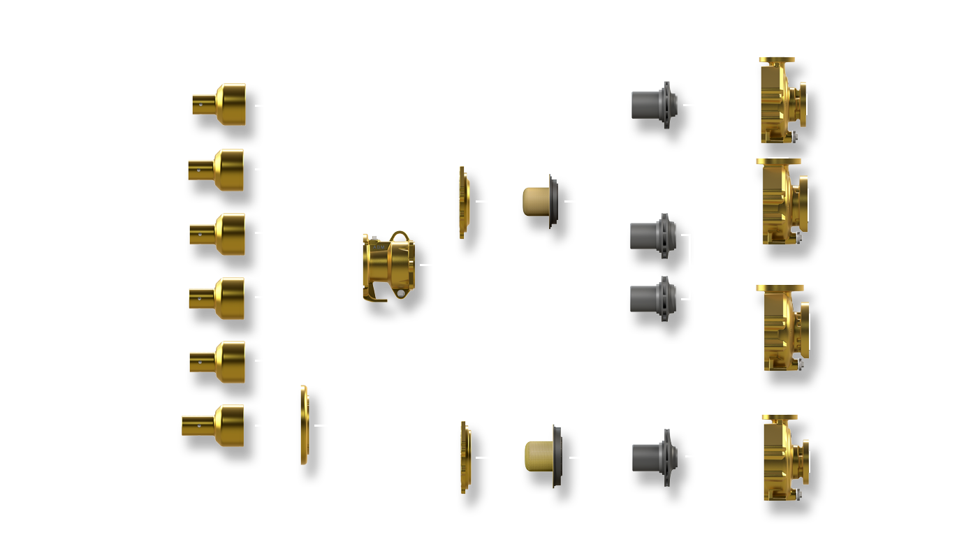
- AP-M pumps have high parts reusage, reducing inventory and complexity. AP-M pump dimensions conform to ASME B73.3 for sealless pumps. AP-M mag-drive pumps’ back-pull-out assemblies are interchangeable with AP-S sealed pumps for simple swap-out of drive ends with this patent-pending design.
Interchangeability
Proven, Robust Design
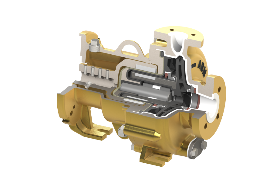
The traditional magnetic drive pump design is well established in most pumping industries. ABM pump products build on legacy designs and improve upon them to provide a more reliable, high-performance pump.
Heavy-Duty Construction:
- The pump was designed from the ground up with durability and reliability foremost. The ductile iron casing, cover and adapter were designed to withstand all static nozzle loads and dynamic operating loads.
- Metal-to-metal fits ensure optimal concentricity between motor, outer drive, and impeller magnet assembly.
Minimized Radial Loads:
- Radial loads in AP-M pumps are minimized using a modified concentric casing volute. All remaining radial loads are absorbed with minimal deflection in the stationary shaft which is cantilevered from the base of the containment shell in a metal-reinforced socket. Optimal NPSH performance of the impeller is achieved with no shaft or shaft support obstruction impeding flow into the impeller eye.
Axial Thrust Balancing
Discharge pressure acts on the axial impeller faces generating axial forces called thrust which are proportional to the total surface area of the impeller. There is inherently an imbalance in those forces that will push the impeller forward toward the suction, creating the need for thrust wear surfaces. This wear causes inefficiency and excess mechanical stress for pumps without a means to balance thrust forces. Many attempts have been made at reducing or eliminating these thrust loads in magnetic drive pumps.
The industry benchmark for magnetic drive thrust balancing has been improved upon in AP-M pumps. The AP-M thrust balancing system has been designed intentionally to improve upon common failures in competitor designs without compromising balancing performance. Common failures occurred when delicate silicon carbide components were chipped or cracked, whether from improper assembly or upset operating conditions. Low viscosity and low vapor pressure liquids have also been a challenge for competitor products, often resulting in vapor bubbles forming on bearing surfaces leading to bearing failure.
Thrust surfaces at the front and back wear ring limit total axial movement of the impeller during startup, shutdown, or upset conditions. The critical valve which makes thrust balancing work is protected from contacting the shaft in any situation. Similar competitor thrust balancing systems do not have this feature, which leads to complete thrust balancing failure and ultimately pump failure. No more chipped shafts!
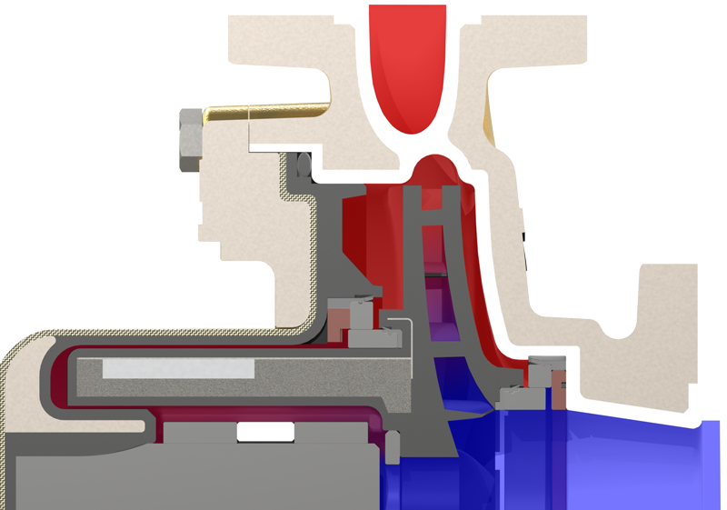
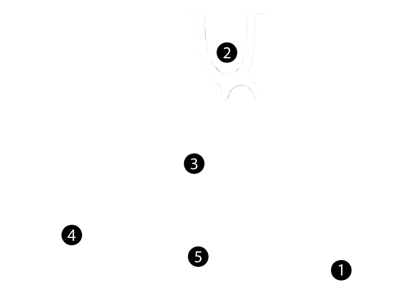
How It Works:
- 1. Flow enters the impeller suction and gains pressure as it accelerates through the impeller blades.
- 2. The liquid exits the pump and pressurizes the downstream piping. A small amount of the total flow recirculates around the impeller lubricating the front and rear wear ring surfaces and creating the flow required for the thrust balance circuit.
- 3. Process liquid passes through the rear wear ring set, filtering out any solids larger than .005in (.127mm). The liquid enters the thrust balance chamber, the volume between the rear wear rings (3) and the balancing valve (5). It is the pressure in the balance chamber that provides the balancing force to eliminate axial thrust loads completely.
- 4. Pressurized, clean process liquid flows around the impeller radial bearings both cooling and lubricating the wear surfaces.
- 5. The thrust balancing valve regulates flow through the thrust balance circuit. It works as a variable orifice, constantly adjusting flow and pressure behind the impeller.
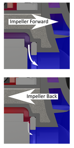
- When pressure behind the impeller is too large, the impeller is forced toward the suction. When that happens, the valve-to-shaft gap opens and allows more liquid to flow from the balance chamber. When the axial forces are balanced, the impeller stops moving.
- Similarly, when the pressure in the balance chamber is too low, the impeller is forced backwards toward the motor. The valve-to-shaft gap closes, restricting the flow from behind the impeller, increasing the balance chamber pressure and eliminating the total axial thrust loads.
- The system automatically, dynamically adjusts to any operating condition across the pump curve, liquid properties, and system fluctuations.
- Since axial loads are dynamically balanced at every operating condition, AP-M pumps may safely operate at any flow rate across the pump’s performance curve. Most mechanically sealed pumps can only operate within 80-120% of the best efficiency point due to unacceptably high radial and axial loads, however AP-M pumps may safely operate anywhere from minimum flow to end of curve.
Fully Bonded ETFE Lining
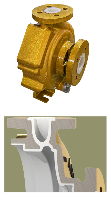
- Ductile iron is known for its toughness and ability to withstand impact and high-pressure conditions. With the fully bonded ETFE lining providing a chemical and abrasion-resistant barrier, the overall structure is better protected from both mechanical and chemical stresses. The thick ETFE lining is almost universally chemically inert. Users no longer need to pay for expensive high alloys that take months to deliver.
- The ETFE lining offers excellent resistance to abrasion and erosion, which is particularly beneficial in applications where the pump handles abrasive slurries or particulates. Wear on the casing and containment shell is minimized maintaining high performance over time.
- ETFE has a low friction coefficient which, when processed into AP-M casings, results in a smoother internal surface for fluid flow. This helps maintain the pump’s hydraulic efficiency by reducing turbulence and minimizing energy losses during operation.
- Back pull-out design for simplified maintenance. Top centerline discharge is self-venting.
- FEP encapsulated FKM o-rings are the standard for sealing the casing to containment shell, providing reliable zero-leak sealing. Other materials are available.
- Designed to withstand ANSI/HI 9.6.2 flange loads.
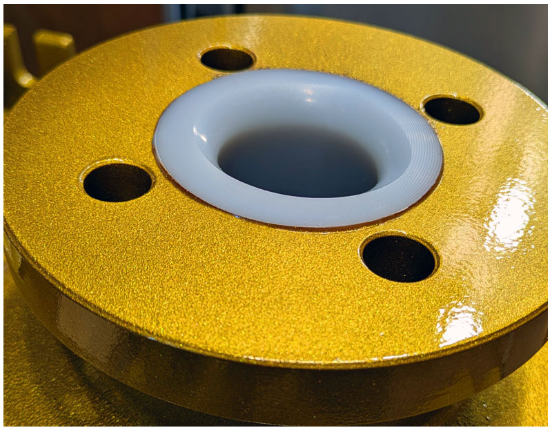
- Flanges match ANSI Class 300 overall diameter and thickness and may be drilled with ANSI Class 150 or 300, ISO PN 16 or 25, or JIS 10K bolt patterns. Flanges have ETFE raised face.
- Casings have a standard drain to enable proper draining and flushing before maintenance, improving maintenance personnel safety.
Impeller
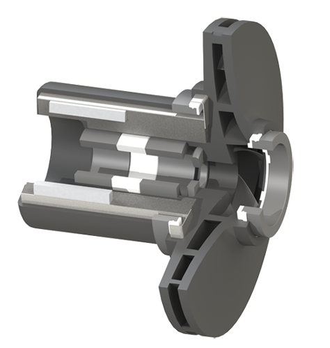
- Carbon-fiber reinforced ETFE provides the ultimate in strength and chemical compatibility. It is injection molded as a single piece forming the impeller and inner magnet assembly providing increased mechanical strength.
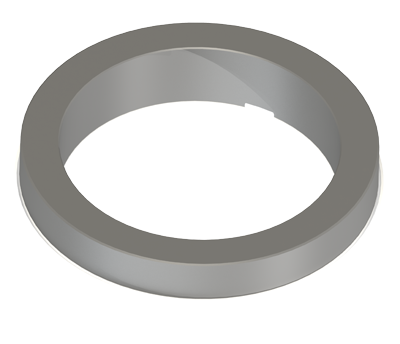
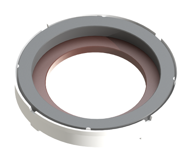
- Replaceable silicon carbide wear ring set maintains optimal performance by reducing leakage back to the suction. Behind the impeller, the wear rings prohibit solids from entering the shaft and bushing area, keeping the thrust balance circuit clog-free.
- The suction is unobstructed resulting in high efficiency and low NPSHR.
- Closed impeller reduces thrust loads. The remaining thrust loads are balanced by the dynamic thrust balancing circuit.
- Capable of passing solids up to 30% by volume if the particle size fits through the impeller passages.
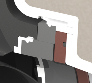
- Wear rings simply snap into place without requiring any special tools or locking pins.
Impeller Radial Bearings:
Two alpha-sintered silicon carbide (SIC) bearings are press-fit into the impeller. The PTFE spacer ensures proper spacing. The large bearing surface area guarantees a long wear life, but the bearings are individually replaceable.
The thrust balance circuit extends the bearing lifetime in two ways. First, the fluid flow actively cools the bearings both OD and ID and since they are in a pressurized environment, the liquid film lubricates the bearing and shaft interface continuously – even with low vapor pressure liquids.
The suction is unobstructed resulting in high efficiency and low NPSHR.
Fully Encapsulated Inner Magnet:
Powerful neodymium magnets ensure reliable torque transfer into the impeller from the outer drive. The magnets are first protected from the process liquid with a single piece injection molded reinforced ETFE plastic layer. Beneath the ETFE layer is an additional layer of stainless steel hermetically sealed over the magnets, providing extreme corrosion and permeation resistance.
One magnet size per pump size minimizes inventory and eliminates compatibility issues where competitor products have multiple magnetic couplings for each pump size.
Simple Wear Ring Installation
ABM sealed and sealless pumps eliminate complicated wear ring installation and retention common among competitor products. The patent-pending wear rings are integrally molded with locking plastic tabs which hold and align the silicon carbide rings and lock them into place. This mechanism provides a means for holding the wear ring in place but also enables the stationary wear to be self-aligning, allowing for tighter clearances. If a wear ring breaks, simply remove any remaining pieces and press a new ring into the pocket. There are no retaining rings, locking pins, or other steps required.
Non-Metallic Containment Shell
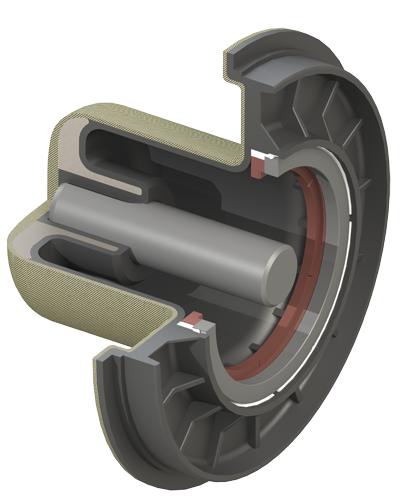
- Carbon fiber-reinforced ETFE forms the inner, chemically inert barrier against the process liquid while an aramid-fiber composite outer shell provides rigidity, strength, and shock resistance to the shell. Eddy current losses which cause heat generation and power loss are eliminated since the magnetic field does not intersect a metallic barrier.
- The integrally molded metal shaft socket reinforcement in the containment shell provides the ultimate rigidity and support for any dynamic loads.
- The heavy-duty construction makes the containment shell water hammer resistant with burst pressures greater than 3000psi, giving the AP-M pump exceptional tolerance to sudden system upsets.
Outer Magnet Assembly
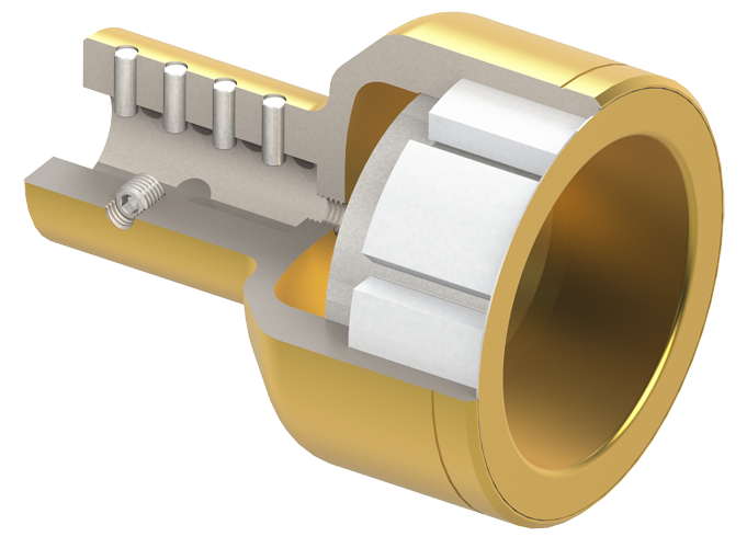
- The high strength Neodymium magnets provide torque to the impeller through the containment shell without slip or eddy current losses. Installation is simplified using dowel pins and set screws to engage the motor shaft. A simple OD groove provides a location marker for proper axial placement on the motor shaft. A stainless-steel cover keeps the magnets clean and protects them from damage and corrosion.
- The adapter has an integrated ‘bump ring’ designed to prevent contact between the outer drive and containment shell, and thereby loss of containment, in the very unlikely event of motor bearing failure.
- One outer magnet size per motor frame minimizes inventory.
Corrosion Protection
- All metal surfaces are painted with a two-part epoxy primer and topcoat for the ultimate resistance to corrosion.
Dimensions


Parts List